Hi all,
Now I have a good camera pcb and I can test again the driver. My board is
an overo gumstix board.
Aguirre Rodriguez, Sergio Alberto wrote:
Hi Michael,
-----Original Message-----
From: linux-omap-owner@xxxxxxxxxxxxxxx
[mailto:linux-omap-owner@xxxxxxxxxxxxxxx] On Behalf Of michael
Sent: Sunday, October 04, 2009 7:29 PM
To: Nishanth Menon
Cc: linux-omap@xxxxxxxxxxxxxxx; linux-media@xxxxxxxxxxxxxxx
Subject: Re: ISP OMAP3 camera support ov7690

Hi,

cc: linux-media

Nishanth Menon wrote:
michael said the following on 10/03/2009 06:13 PM:
I'm writing a driver to support the ov7690 camera and I have some
question about the meaning of:

- datalane configuration
CSI2 Data lanes - each CSI2 lane is a differential pair.
And, at least 1
clock and data lane is used in devices.
Sorry can you explain a little bit more. I have the camera
connected to the
cam_hs and cam_vs and the data is 8Bit. I use the the isp init
structure. The sccb bus works great and I can send
configuration to it,
but I don't receive any interrupt from the ics, seems that it
doen't see
the transaction:

The ISPCCDC: ###CCDC SYN_MODE=0x31704 seems ok.


static struct isp_interface_config ov7690_if_config = {
        .ccdc_par_ser           = ISP_CSIA,
        .dataline_shift         = 0x0,
        .hsvs_syncdetect        = ISPCTRL_SYNC_DETECT_VSFALL,
Can you try with ISPCTRL_SYNC_DETECT_VSRISE ?
        .strobe                 = 0x0,
        .prestrobe              = 0x0,
        .shutter                = 0x0,
        .wenlog                 = ISPCCDC_CFG_WENLOG_AND,
        .wait_hs_vs             = 0x4,
        .raw_fmt_in             = ISPCCDC_INPUT_FMT_GR_BG,
        .u.csi.crc              = 0x0,
        .u.csi.mode             = 0x0,
        .u.csi.edge             = 0x0,
        .u.csi.signalling       = 0x0,
        .u.csi.strobe_clock_inv = 0x0,
        .u.csi.vs_edge          = 0x0,
        .u.csi.channel          = 0x0,
        .u.csi.vpclk            = 0x1,
        .u.csi.data_start       = 0x0,
        .u.csi.data_size        = 0x0,
        .u.csi.format           = V4L2_PIX_FMT_YUYV,
};

and I don't know the meaning of

lanecfg.clk.pol = OV7690_CSI2_CLOCK_POLARITY;
lanecfg.clk.pos = OV7690_CSI2_CLOCK_LANE;
lanecfg.data[0].pol = OV7690_CSI2_DATA0_POLARITY;
lanecfg.data[0].pos = OV7690_CSI2_DATA0_LANE;
lanecfg.data[1].pol = OV7690_CSI2_DATA1_POLARITY;
lanecfg.data[1].pos = OV7690_CSI2_DATA1_LANE;
lanecfg.data[2].pol = 0;
lanecfg.data[2].pos = 0;
lanecfg.data[3].pol = 0;
lanecfg.data[3].pos = 0;
This is the physical connection details:

- The .pol field stands for the differntial pair polarity.
  (i.e. the order in which the negative and positive connections
  are pugged in to the CSI2 ComplexIO module)
What exact the meaning of the pol, sorry? I have a signal that is connected
to a pin. If the pos is avalaible can I use it?
It's not important how to route the signal but don't route on the same lane.
Is it right?
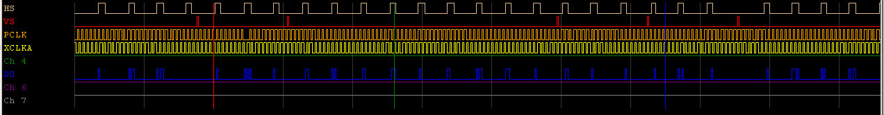
This is the timing of the camera so I can check signal, but I don't receive interrupt
of isp engine
The camera is direct connected to the
camera omap camera signal and using the oscilloscope I can see the hs/vs signal
The hs is low and go up, like the vs signal. I have only one camera
with that use D0 to D7 data bit.

http://www.gumstix.net/Hardware/view/I/O-connectors-cabling/Gumstix-Overo-27-pin-connector-J5-to-manage-camera-controls/112.html

static struct isp_interface_config ov7690_if_config = {
       .ccdc_par_ser           = ISP_CSIA,
       .dataline_shift         = 0x0,
       .hsvs_syncdetect        = ISPCTRL_SYNC_DETECT_VSRISE,
       .strobe                 = 0x0,
       .prestrobe              = 0x0,
       .shutter                = 0x0,
       .wenlog                 = ISPCCDC_CFG_WENLOG_AND,
       .wait_hs_vs             = 0x4,
       .raw_fmt_in             = ISPCCDC_INPUT_FMT_GR_BG,
       .u.csi.crc              = 0x0,
       .u.csi.mode             = 0x0,
       .u.csi.edge             = 0x0,
       .u.csi.signalling       = 0x0,
       .u.csi.strobe_clock_inv = 0x0,
       .u.csi.vs_edge          = 0x0,
       .u.csi.channel          = 0x0,
       .u.csi.vpclk            = 0x1,
       .u.csi.data_start       = 0x0,
       .u.csi.data_size        = 0x0,
       .u.csi.format           = V4L2_PIX_FMT_YUYV,
};

This is my initial configuration
#define OV7690_CSI2_CLOCK_POLARITY      0       /* +/- pin order */
#define OV7690_CSI2_DATA0_POLARITY      0       /* +/- pin order */
#define OV7690_CSI2_DATA1_POLARITY      0       /* +/- pin order */
#define OV7690_CSI2_CLOCK_LANE          1        /* Clock lane position: 1 */
#define OV7690_CSI2_DATA0_LANE          2        /* Data0 lane position: 2 */
#define OV7690_CSI2_DATA1_LANE          3        /* Data1 lane position: 3 */
tim#define OV7690_CSI2_PHY_THS_TERM        2
#define OV7690_CSI2_PHY_THS_SETTLE      23
#define OV7690_CSI2_PHY_TCLK_TERM       0
#define OV7690_CSI2_PHY_TCLK_MISS       1
#define OV7690_CSI2_PHY_TCLK_SETTLE     14

With this clock polarity

lanecfg.clk.pol = OV7690_CSI2_CLOCK_POLARITY;
lanecfg.clk.pos = OV7690_CSI2_CLOCK_LANE;
lanecfg.data[0].pol = OV7690_CSI2_DATA0_POLARITY;
lanecfg.data[0].pos = OV7690_CSI2_DATA0_LANE;
lanecfg.data[1].pol = OV7690_CSI2_DATA1_POLARITY;
lanecfg.data[1].pos = OV7690_CSI2_DATA1_LANE;
lanecfg.data[2].pol = 0;
lanecfg.data[2].pos = 0;
lanecfg.data[3].pol = 0;
lanecfg.data[3].pos = 0;
isp_csi2_complexio_lanes_config(&isp->isp_csi2, &lanecfg);

Michael